Day 3 - NHG Training
- by Paul Freakley
- •
- 13 Dec, 2017
- •
Training in Notting Hill Gate

Wednesday 13th December - Day 3
Four degrees Celsius was a rather better start to the day with the bonus of no car defrosting. A team building exercise is on the menu for the third Engineer training day at the Eagle Lab in Notting Hill Gate.
On my arrival to the workshop the talk is around the strange and worrying smell the other engineers experienced while laser cutting material after my departure yesterday. As Ash had been experimenting with an Air Quality sensor yesterday a comment was made that it would have been a useful tool to warn if the filter system fails.
What a perfect subject for the team project. White board commandeered, coloured pens, coffee, tea, pads and pens at the ready, its brainstorming time. Lots of ideas fly around the room, some useful, some not so useful, some very funny and even some fantastic ideas if we had the budget of the International Space Agency, a new aircraft carrier or both.
The colourful diagram and flow chat on the white board looks impressive and very feasible to achieve in the allocated time. We decide to fully exploit the small but powerful Micro:Bit. In particular the radio function.
Project - Four Micro:Bits with an Air Quality sensor connected to each will be placed in the corners of the Lab. (Hannah aptly names these Ashley, Charlie, Dan and Hannah). A central control Micro:Bit sends a radio message to each of the sensor Bits in turn requesting the air quality value. Hannah calls this one Paul as it’s in control and bossy (thanks Hannah). The cool, suave master control unit collates this data, calculates the room average, processes the values and triggers an alarm condition if levels are too high.
The second part of this project is a number of output devices that can be triggered when an alarm condition occurs. Each output device is another Micro:Bit that has components added such as a LED’s, servos, Neopixels or a relay to control a fan. The master control sends a radio message to one or more output devices to try and correct the alarm condition or warn the occupants.
This project is just a proof of concept as a working prototype example using remote sensing and control with wireless communication.
Details – Our whiteboard sets out the data protocols that are communicated between the stations. Each sensor waits for a request for information. The master sends a string “lp1” (Level Please to sensor 1), “lp2” to sensor 2 and so on. When the sensor receives a string it checks if it contains its own id (1,2,3 or 4) and if yes, sends back a three digit air quality data value prefixed with its id number. So a value of 222 becomes 4222 from sensor 4. The master sends a request to each sensor in turn and stores the value as separate variables. A quick check is made to ensure all four reads are valid before calculating an average and displaying value on the masters led matrix. Each of these values are compared with a threshold value and if above, a packet of data is sent out to activate one or more of the output devices. The alarm data is a two digit code with the first digit being the id and second digit is 1 for on and 0 for off. So to turn on device 2 we send 21 and to turn if off we send 20.
In addition, each sensor displays an air quality level from 0 to 9 on its own display for quick reference. Button B once pressed overrides the sensor read with a high level to test the alarm condition on the next read from the master. Each output device also uses button B to turn that device on for 5 seconds as a test.
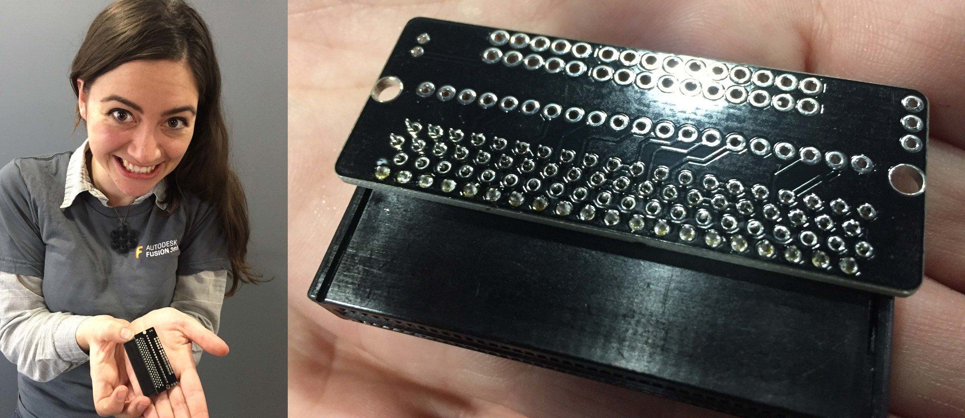
Delegation - Ash does great work connecting the sensors to Micro:bits and coding, Dan generates Micro:bits to transmit test sequences for intermediate testing then sets to work with Charlie building someoutput devices. Hannah works on the master code with myself before soldering all the Micro:bit edge connector PCB’s. Lots of intermediate testing shows good progress and everything is working fine.
We all then finally concentrate on the hardware interfacing for the output devices. Dan creates a simple LED display and servo, Charlie uses a small Neopixel strip and I create the relay controlled fan. Ash is ahead so we decide to add a fifth output device with a Neopixel ring to display the average room level. The added master code now sends a 5 for the this device id and values 0 to 9 for the level. So 50 is minimum and 59 max. The higher the level the more LED’s light and more intense the colour.
Finished - we take our 4 sensors, 4 output devices, room status display and master control unit into the main room for a demonstration test. All is looking good. I would love to say it all worked first time. But it didn’t. After few tests we discover that all four sensor data values are not being received. I am sure we can sort this quickly but we have run out of time today.
Tomorrow it will be working (fingers don’t need to be crossed either).
More updates with pictures to come.


